Horizontal orientation pressure filters solve the headroom constraint that prevents installation of tall vertical vessels inside existing buildings, below ground structures or within process skids. Factory-assembled with multiple top-access manholes, automated valve stations and pre-wired PLC control panels, horizontal filters are delivered to site as plug-and-play units requiring only inlet, outlet and drain connections.
Design and engineering guide for pressure multimedia filter installations. Vessel sizing, manifold layout, backwash automation and commissioning for drinking water treatment at 5-100 MLD.
Multimedia Filter by Reynolds & Bauhm. Industrial water and wastewater treatment solutions engineered for efficiency, durability and worldwide compliance.
316L stainless steel vertical pressure filter vessels with hopper conical bottom for food, beverage, pharmaceutical and high-purity process water. CIP-compatible, sanitary fittings, ASME BPE.
SCADA and control system integration for critical water treatment processes plants. Real-time monitoring, data logging, alarms and remote access.
The choice between horizontal and vertical vessel orientation is primarily driven by available headroom, media access requirements and site logistics. Horizontal vessels require more floor area per unit volume but fit beneath pipebridges, within containerised packages and in retrofit applications where the building height cannot be modified.
A 2.0 m diameter horizontal vessel requires only 2.2–2.5 m clear height (vessel plus legs and valve clearance) compared with 5.0–6.0 m for an equivalent-volume vertical vessel. Horizontal filters are specified for installation in low-headroom pump houses, beneath existing overhead pipework, within ISO shipping container packages, and in basement-level treatment rooms.
Horizontal vessels are fitted with two to four top-mounted bolted manways (DN450 or DN600) spaced along the vessel length, giving access to the full media bed without confined-space entry. Media loading and removal is simplified: swing the manway open, probe the bed depth from above, extract media by vacuum tanker from the manway or through the bottom drain nozzle. No scaffolding required.
Horizontal filter skids are assembled at the fabrication workshop with vessel, valves, local instrumentation (differential pressure transmitter, flow meter, pressure gauges), PLC panel and all inter-connecting pipework mounted on a common structural steel skid. The complete assembly is FAT-tested at the factory and arrives on site as a single lift, reducing installation time to 1–2 days for two-vessel packages.
Horizontal vessels are rated to PED 2014/68/EU Category III for pressures up to 16 bar. Internal coatings: food-grade epoxy (DWI Reg 31 approved) for drinking water duty; rubber-lined for aggressive pH < 5 or high-chloride feeds. External: epoxy primer plus polyurethane topcoat in customer-specified RAL colour. Stainless steel (316L) horizontal vessels available for pharmaceutical and food-grade applications.
| Parameter | Horizontal Vessel | Vertical Vessel | Decision Factor |
|---|---|---|---|
| Minimum installation height | 2.0–2.5 m | 4.5–6.5 m | Use horizontal if headroom < 3.5 m |
| Floor footprint (per m³ vessel volume) | Higher | Lower | Use vertical if floor space is constrained |
| Media removal access | Multiple top manways — easy | Single top manway or side entry | Horizontal easier for frequent media changes |
| Inlet flow distribution | Requires internal header distributor | Natural central distribution | Vertical slightly simpler hydraulics |
| Factory pre-assembly | Ideal — complete skid | Skid possible up to 1.5 m dia | Horizontal preferred for modular packages |
| Backwash efficiency | Uniform if distributor designed correctly | Uniform — full cross-section | Equivalent with correct design |
| Transport (road) | Up to 3.5 m dia on standard trailer | Height limits above 3.0 m | Horizontal preferred for large-diameter vessels |
Survey available headroom at the installation location: clear ceiling or obstruction height (m), pipebridge or structural beam positions, minimum crane lift height for vessel delivery. If clear height is > 4.0 m: vertical vessels are equally viable and may offer better hydraulics. If < 3.5 m: horizontal is the preferred solution.
Required media volume (m³) = filter area (m²) × media bed depth (m). For horizontal vessels, the effective filter cross-section varies with vessel diameter and fill level — manufacturer sizing tools calculate effective filter area for a given L:D ratio (typically 2:1 to 3:1). Verify hydraulic loading rate on the effective cross-section, not the nominal diameter.
Specify a full-length internal header-lateral distributor (perforated or slotted pipe) running the vessel axis to ensure uniform flow distribution across the media cross-section. Header open area: 1.5–2.5% of vessel cross-section. Lateral spacing: 200–300 mm centres. This is critical for horizontal filters — poor distribution causes media channelling and short-circuit flow.
Position top manways at 1.0–1.5 m spacing along the vessel centreline. Minimum two manways for vessels up to 4 m long; three or more for longer vessels. Specify flush-mounted manway frames so media does not accumulate at the rim. Nozzle schedule: inlet (flanged, top or end), outlet (flanged, bottom or end), drain, vent, sample point, instrument tappings (×3 for ΔP measurement along vessel length).
Factory-mount the PLC panel on the vessel skid or on a local stand within 3 m. Backwash sequence for horizontal filter: (1) close inlet; (2) open air scour (upward through underdrain laterals 3–5 min); (3) open backwash water supply (10–15 min); (4) open backwash waste; (5) rinse. Monitor ΔP across vessel length via three tapping points to detect channelling during operation.
Pressure-test assembled skid at 1.5× working pressure for 30 min. Cycle all actuated valves through 10 open/close sequences and confirm response times meet specification (< 30 s for DN200 and below). Test backwash sequence from PLC HMI. Witness test by client representative before despatch. Provide CE Declaration of Conformity to PED and all material certificates.
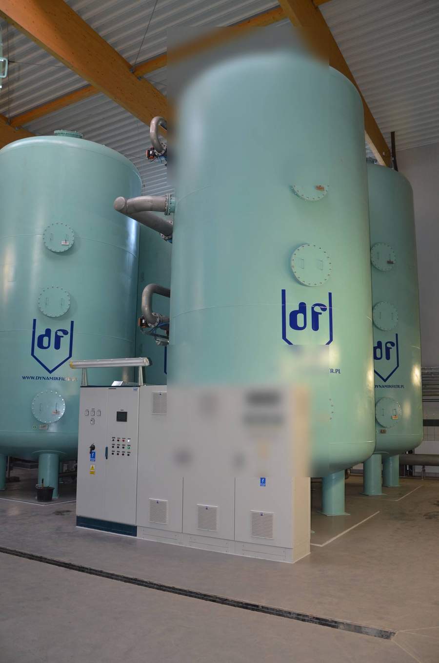
Large-scale indoor vertical filter installations for municipal drinking water treatment.
Read MoreMedia configurations, SDI performance and backwash design for pressure filter vessels of any orientation.
Read MoreFood-grade vertical SS pressure filters with conical discharge for pharmaceutical and process water.
Read MoreShare your headroom, flow rate and inlet quality. We will size a horizontal filter skid that fits your space and delivers your treated-water target.
Request Horizontal Filter SizingOur expertise spans multiple industries with sector-specific water treatment solutions.