Large-scale filter installations housing multiple rows of pressure multimedia filter vessels are the standard civil engineering solution for drinking water treatment upgrades at 5–100 MLD capacity. Epoxy-coated carbon steel vessels, a shared stainless steel valve manifold gallery and centralised backwash infrastructure combine high throughput with minimal footprint.
Multimedia Filter by Reynolds & Bauhm. Industrial water and wastewater treatment solutions engineered for efficiency, durability and worldwide compliance.
Engineering guide to horizontal pressure filter vessels for low-headroom sites. Factory-assembled skid units with multiple manways, automated backwash PLC and full PED compliance.
316L stainless steel vertical pressure filter vessels with hopper conical bottom for food, beverage, pharmaceutical and high-purity process water. CIP-compatible, sanitary fittings, ASME BPE.
Engineering guide for Granular Activated Carbon (GAC) contactor installations for drinking water treatment. EBCT calculation, vessel sizing, outdoor civil installation, media selection and DWI.
A purpose-built filter installation protects pressure vessel installations from weather, frost and UV degradation while providing a controlled environment for valve maintenance, media sampling and backwash monitoring. The layout is engineered around the shared pipework gallery running between two parallel rows of vessels.
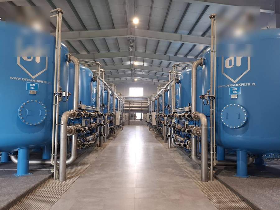
Single-storey steel-framed or concrete-block buildings with reinforced concrete plinth beams supporting vessel legs. Floor grading (1:100 minimum) to a central drain channel handles backwash overflow and spillage. Minimum clear height 1.0 m above vessel tops for manway access; aisle width ≥ 1.2 m between vessel rows and ≥ 0.8 m at perimeter for valve maintenance.
Cylindrical pressure vessels in SA-516 Grade 70 carbon steel, epoxy-coated internally (food-grade drinking water approved coating to DWI Regulation 31 / NSF 61). Working pressure 6–10 bar; test pressure 1.5× WP. Vessel diameters 1.0–3.0 m; standard heights 2.0–3.5 m plus domed ends. Each vessel fitted with: top manway (DN450 or DN600 bolted), bottom drain/media outlet, inlet distributor, underdrain lateral system, pressure gauge tapping and sample point.
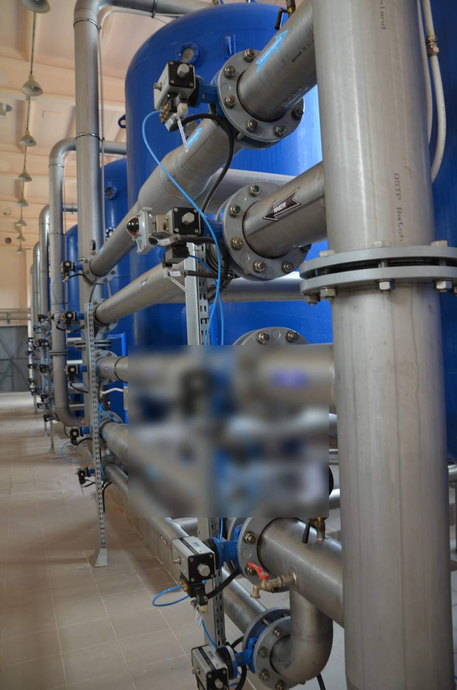
The inter-row pipework gallery carries common inlet header, filtered water header, backwash water supply and backwash waste headers in schedule-40 or stainless steel pipework. Each vessel connects via automated butterfly or ball valves (electric or pneumatic actuators) rated for 10 bar. Valve actuator signals wire back to the PLC/SCADA panel sited at one end of the gallery. Manifold design allows any single vessel to be isolated for maintenance without interrupting flow to adjacent vessels.
Filter hall SCADA manages individual vessel backwash sequences triggered by differential pressure (ΔP ≥ 0.4 bar across media bed) or elapsed service time (typically 18–30 h). Backwash sequence: (1) close inlet valve; (2) open backwash supply; (3) air scour 3–5 min at 40–60 m³/h/m²; (4) water backwash 8–15 min at 20–30 m³/h/m²; (5) rinse to waste; (6) return to service. Only one vessel per bank backwashes at a time to maintain output.
| Parameter | Typical Range | Design Basis | Standard Reference |
|---|---|---|---|
| Hydraulic loading rate | 10–20 m/h (15 m/h typical) | Filter media D10 and inlet turbidity | BS EN 12255-10; AWWA B100 |
| Vessel diameter | 1.0–3.0 m | Flow per vessel ÷ hydraulic loading | PD manufacturer sizing |
| Number of vessels | 4–24 per bank | Total flow ÷ (vessel area × HLR) + 1 standby | CIWEM guidance |
| Media bed depth | 800–1,200 mm (MMF) | Anthracite 400–600 mm + sand 300–500 mm + gravel 150–200 mm | WRc filter media guidelines |
| Working pressure | 4–8 bar (inlet) | Upstream pump head minus friction losses | PED 2014/68/EU |
| Backwash water demand | 3–6% of throughput | Backwash rate × duration × frequency | Site water balance |
| Service run length | 18–36 h (inlet TSS < 10 mg/L) | Media holding capacity | Pilot data or design standard |
Establish peak, average and minimum design flows (m³/h). Characterise inlet water: turbidity (NTU), TSS (mg/L), SDI15, temperature range, pH, hardness. Define treated-water quality targets: TSS < 1 mg/L, turbidity < 0.1 NTU for drinking water, SDI15 < 3 for RO pretreatment. These three inputs drive all subsequent vessel sizing calculations.
Calculate required filter area (m²) = peak flow (m³/h) ÷ HLR (m/h). Select standard vessel diameter; calculate number of vessels = filter area ÷ vessel cross-section, rounding up to next integer, plus one standby. Arrange in two parallel rows for manifold economy. Confirm building footprint against site constraints.
For MMF: anthracite ES 0.8–1.0 mm (300–500 mm depth), silica sand ES 0.5–0.7 mm (300–500 mm), support gravel 2–16 mm (150–200 mm). Confirm UC (uniformity coefficient) < 1.6 for anthracite and < 1.4 for sand. Obtain DWI Regulation 31 approval for drinking water contact. For GAC duty: EBCT calculation determines carbon bed depth and vessel height.
Size manifold headers for max velocity 1.5 m/s in stainless steel (lower friction loss and hygienic). Size backwash supply for simultaneous air scour and water wash of one vessel. Specify actuated valves with fail-safe positions (inlet fail-closed; backwash waste fail-open). Route backwash waste to holding tank (sized for 1 full backwash cycle volume) before recycling to works inlet.
Coordinate vessel plinth heights with inlet and outlet pipe inverts. Specify floor drain capacity for full backwash overflow scenario. Provide vessel access platforms at manway height (typically 2.0–3.0 m AFF). Lighting: minimum 300 lux at floor level; 500 lux at control panels. Ventilation: 6 air changes/hour minimum to control condensation on cold vessels.
Fill vessels with demineralised or potable water before media loading to prevent air locking. Condition media with 3–5 backwash cycles before placing on duty. Commission SCADA backwash sequences with graduated ΔP setpoints. Verify outlet quality against design targets at 25%, 50%, 75% and 100% design flow. Run 30-day performance test before Practical Completion sign-off.
Full technical specification for MMF media configurations, hydraulic loading, SDI performance and backwash design.
Read MoreWhen limited headroom or retrofit site constraints favour horizontal vessel orientation.
Read MoreGranular activated carbon filter bank design for taste, odour, organics and micropollutant removal in drinking water.
Read MorePLC backwash sequencing, differential pressure monitoring and SCADA integration for automated filter installation operation.
Read MoreSend us design flow, inlet water quality and site constraints. We will provide vessel count, building footprint and full P&ID for your filter installation.
Request Filter Installation DesignOur expertise spans multiple industries with sector-specific water treatment solutions.