P&ID drawings to ISA-5.1 and BS EN 1069 standards with full line numbering, instrument tagging, valve specifications, and cause-and-effect matrices. HAZOP-ready documentation for safety reviews.
Intelligent 3D plant modelling in AutoCAD Plant 3D, AVEVA E3D, and Bentley OpenPlant.
Complete plant layout, piping design, and engineering drawing services.
Intelligent pipe routing with clash detection, slope optimisation, and support span validation.
Spool fabrication isometrics with weld mapping, material lists, and dimensional take-offs.
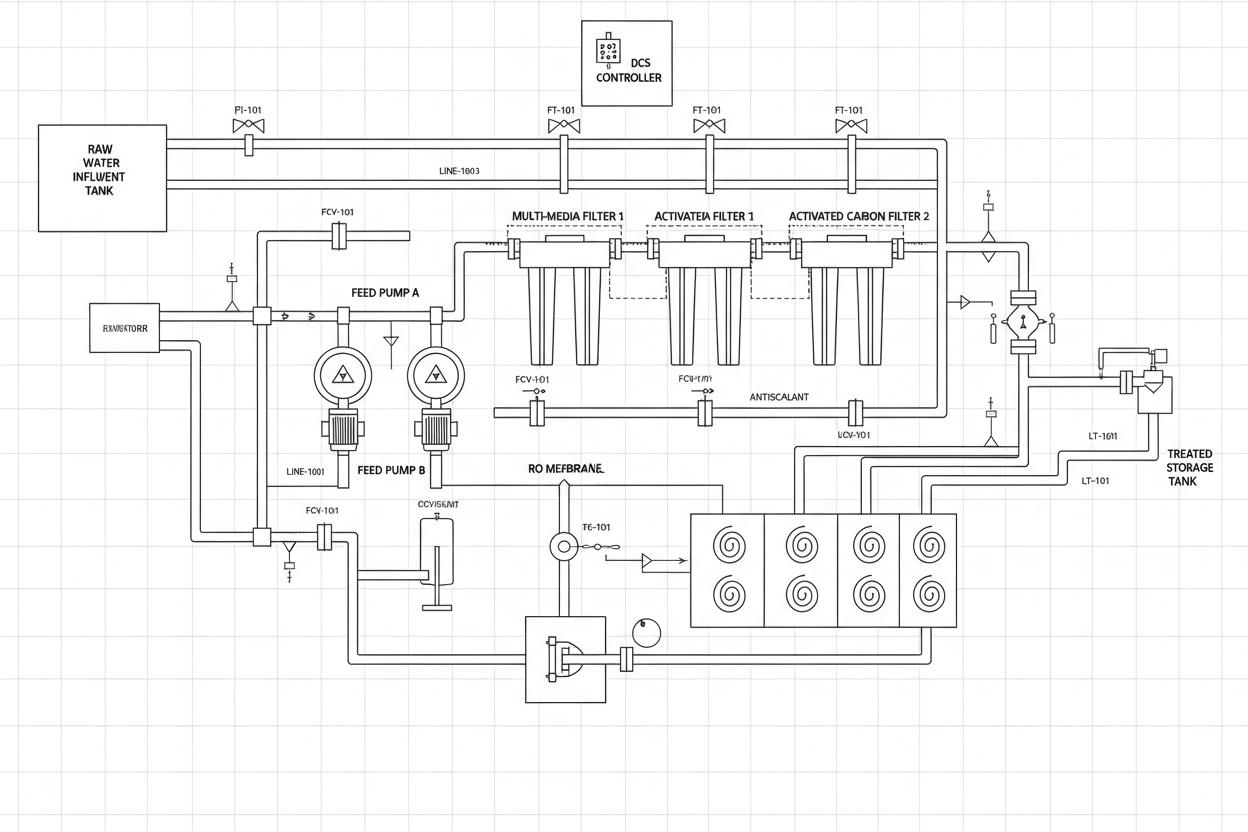
P&ID with ISA symbology, line numbers, and instrument tags
The Process and Instrumentation Diagram (P&ID) is the definitive technical document that defines how a plant operates. It shows every piece of equipment, every pipe, every valve, every instrument, and every control loop in a standardised symbolic format that is understood by process engineers, operators, construction teams, and regulatory inspectors worldwide. A well-drafted P&ID is the foundation of safety reviews, HAZOP studies, control system design, operator training, and maintenance planning.
Reynolds & Bauhm produces P&IDs to ISA-5.1 and BS EN 1069 symbology standards with full line numbering, instrument tagging, valve specifications, and cause-and-effect matrices. We develop P&IDs from process flow diagrams, PFDs, and process descriptions; iterate through HAZOP and SIL assessments; and issue construction P&IDs with full instrument datasheets and I/O lists.
Vessels, tanks, pumps, compressors, heat exchangers, and package units shown with ISA standard symbols, equipment numbers, and design duty annotations.
Every pipe identified with unique line number containing service, specification, size, insulation, and tracing codes per client or project standards.
Manual, motorised, pneumatic, and control valves with line size, rating, material, actuator type, and fail position indicated on drawing or in valve list.
Transmitters, switches, gauges, analysers, and control loops with ISA tag numbers (FT, PT, TT, LT, etc.), ranges, and I/O types defined.
Relief valves, rupture discs, safety showers, fire protection, and ESD systems shown with trip setpoints and cause-and-effect references.
Steam, cooling water, instrument air, nitrogen, and effluent headers with supply and return indication and tie-in points.
Consolidated process and instrumentation diagrams for the complete plant with sheet index, drawing register, and revision history.
Complete pipe line registers with line numbers, sizes, specifications, design conditions, insulation, testing requirements, and painting specs.
Tag list with instrument type, service, range, setpoints, I/O type, panel location, and datasheet reference for every instrument on the P&ID.
Valve schedule with tag numbers, line sizes, pressure ratings, materials, actuator types, fail positions, and vendor specifications.
Safety matrix showing trip causes (high level, high temperature, etc.) and resulting effects (valve closures, pump stops, alarms) with SIL ratings.
Individual specification sheets for transmitters, switches, control valves, and analysers with process data, electrical, and mechanical requirements.
| ISA-5.1 | Instrumentation Symbols and Identification – primary standard for P&ID symbology in North America and globally |
| BS EN 1069 | Graphical symbols for P&IDs in the UK and European process industries |
| ISO 3511 | Process measurement control functions and instrumentation – symbol representation |
| DIN 19227 | Graphical symbols and identifying letters for process control engineering in German-speaking regions |
| AS 1100.101 | General principles for technical drawing in Australia including P&ID conventions |
| JIS C 0401 | Graphical symbols for instrumentation and control in Japanese industrial standards |
| PIP PIC001 | P&ID symbols and diagramming conventions for Process Industry Practices members |
| Client Standards | Shell DEP, BP EPS, ExxonMobil GP, and other major operator P&ID standards accommodated |
From conceptual layouts to construction-ready drawings, Reynolds & Bauhm delivers complete drafting and modelling services to global standards. Speak with our design engineers to scope your project.
Our expertise spans multiple industries with sector-specific water treatment solutions.