Plan views, elevation drawings, sections, and support details for process pipework. Coordinated with structural steel, electrical cable trays, and HVAC ductwork for clash-free construction.
Intelligent 3D plant modelling in AutoCAD Plant 3D, AVEVA E3D, and Bentley OpenPlant.
Complete plant layout, piping design, and engineering drawing services.
P&ID process and instrumentation diagrams to ISA-5.1 and BS EN 1069 standards.
Intelligent pipe routing with clash detection, slope optimisation, and support span validation.
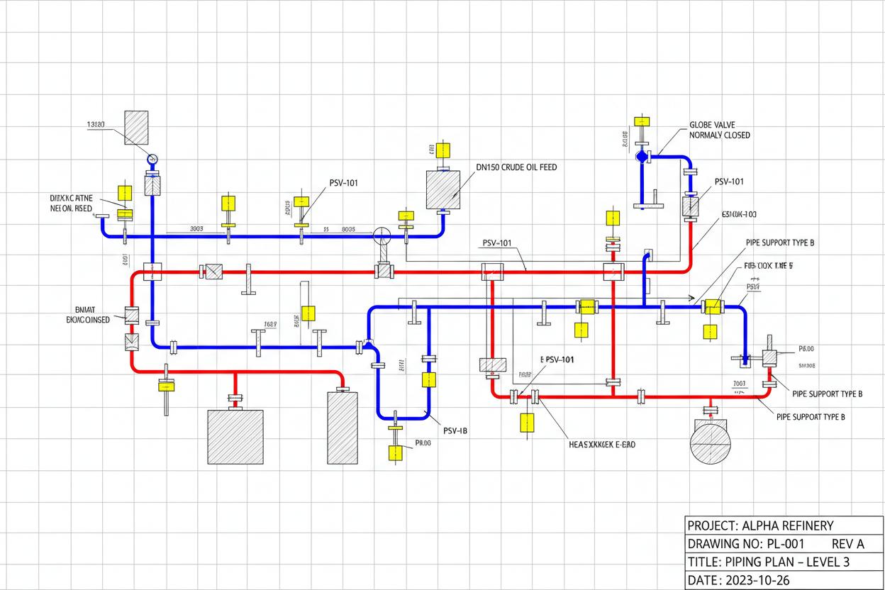
Plan view piping layout with pipe supports and valve stations
Piping layout drawings communicate the spatial arrangement of process pipework to construction teams, inspectors, and maintenance personnel. Plan views show pipe routes in horizontal projection, while elevation views show vertical routing, pipe supports, and clearance over walkways and roadways. Every pipe is shown with its line number, specification, size, insulation, and slope – information essential for fabrication, erection, and future modification.
Reynolds & Bauhm produces piping layout drawings from 3D models or from P&IDs and GA drawings for retrofit projects. We coordinate with structural steel, electrical cable trays, and HVAC ductwork to ensure clash-free installation. Our drawings include pipe support locations, expansion joint placement, valve and instrument accessibility, and hydrotest boundary definitions.
Horizontal projection piping layouts at each elevation level. Show pipe centreline routes, valve stations, instrument locations, and support positions with gridline dimensions.
Vertical projection showing pipe rack tiers, pipe drops, risers, and overhead clearances. Critical for identifying interferences with structural beams and electrical trays.
Cross-sections through pipe racks, trenches, and congested areas. Reveal vertical relationships between pipes, cables, and structure that plan views cannot show.
Detailed support and hanger schedules with load calculations, anchor/guide definitions, and expansion loop geometry for thermal movement accommodation.
Buried pipe route plans with invert levels, bedding details, thrust block locations, and crossing coordinates for sewers, water mains, and chemical lines.
Hydrant, monitor, deluge, and sprinkler piping layouts with coverage verification, hose reel routing, and foam system distribution networks.
| Min Pipe Spacing (flange face) | 25 mm (small bore) to 450 mm (large bore + insulation) |
| Pipe Rack Tier Spacing | 300 – 600 mm between outside diameters |
| Overhead Clearance (walkway) | 2.2 m minimum; 2.5 m preferred |
| Valve Operating Clearance | 300 mm from handwheel to nearest obstruction |
| Instrument Access | 1.0 m clear space in front of transmitters and analysers |
| Slope (gravity drain) | 1:100 to 1:200 towards low point with vent at high point |
| Expansion Loop Width | 20-40x pipe OD depending on thermal expansion and stress |
| Insulation Thickness | 25 – 150 mm (temperature and energy conservation dependent) |
A specialty chemical manufacturer in the Netherlands required re-routing of 42 process lines through a congested pipe rack serving three reactor buildings. The existing rack had evolved over 30 years with no coherent layout, resulting in 12 pipe crossings at grade (creating trip hazards), 8 unsupported spans exceeding 6 m, and 3 instances of 150°C steam pipes directly above solvent lines in violation of ATEX zoning. Reynolds & Bauhm surveyed the existing installation with 3D laser scanning, modelled the complete pipe rack in AutoCAD Plant 3D, and developed a phased rerouting strategy. By relocating low-temperature utility lines to a new secondary rack at 4.5 m elevation, we freed the primary rack for process lines with proper thermal segregation. The new layout eliminated all grade crossings, reduced maximum unsupported span to 3.5 m, and achieved full ATEX zone compliance with 2 m vertical separation between hot and flammable lines. The redesign was implemented during a 3-week summer shutdown with zero safety incidents.
ATEX zone compliance achieved with proper thermal and flammable separation.
All 12 grade crossings eliminated through elevated secondary rack design.
Complete implementation during 3-week summer shutdown window.
From conceptual layouts to construction-ready drawings, Reynolds & Bauhm delivers complete drafting and modelling services to global standards. Speak with our design engineers to scope your project.
Our expertise spans multiple industries with sector-specific water treatment solutions.