Intelligent clash-free pipe routing with spec-driven design, slope optimisation, and support span validation. Reduce field welds by 40%, cut pressure drop by 25%, and eliminate site clashes.
Intelligent 3D plant modelling in AutoCAD Plant 3D, AVEVA E3D, and Bentley OpenPlant.
Complete plant layout, piping design, and engineering drawing services.
P&ID process and instrumentation diagrams to ISA-5.1 and BS EN 1069 standards.
Spool fabrication isometrics with weld mapping, material lists, and dimensional take-offs.
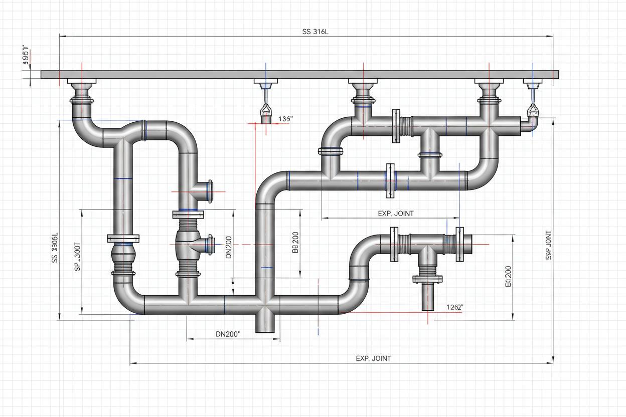
3D pipe routing model with clash detection and support optimisation
Intelligent pipe routing transforms a spaghetti-like tangle of process lines into an orderly, constructible, and maintainable pipe network. Proper routing minimises pressure drop by avoiding unnecessary bends, ensures adequate slope for gravity drainage, maintains proper clearances for insulation and heat tracing, and positions valves and instruments where operators can access them safely. In 3D design environments, routing algorithms can optimise paths automatically while respecting spacing rules, support span limits, and clash boundaries.
Reynolds & Bauhm routes pipes using spec-driven 3D design tools that enforce material specifications, pressure ratings, and connection types automatically. We validate routes against stress analysis requirements, ensure thermal expansion loops are positioned correctly, and verify that every pipe is fully supported without exceeding maximum span distances. Our routing deliverables include bend schedules, cut-length lists, and prefabrication spool definitions that reduce field welding and accelerate construction.
Minimise overall pipe length while respecting access zones, structural boundaries, and equipment maintenance envelopes. Every extra metre adds cost and pressure drop.
Long-radius bends preferred over elbows where possible. Each 90° elbow adds equivalent length of 30-50 pipe diameters to pressure drop calculations.
Gravity drainage lines routed with continuous positive slope. Avoid pockets and sags that create air locks or sediment accumulation in low points.
Expansion loops, offsets, and flexible joints positioned to absorb thermal growth without overstressing anchors or connected equipment nozzles.
Route pipes in sequences that allow prefabrication and modular installation. Consider lifting access, welding positions, and NDT accessibility.
Space for tie-ins, spare branches, and future equipment connections. Document reserve capacity and spare nozzle positions on as-built drawings.
AutoCAD Plant 3D and AVEVA E3D provide spec-driven pipe routing with automatic component placement, branch connections, and support generation. The software enforces piping specifications, material selections, and connection types – preventing specification breaches that cause field delays.
Navisworks federated clash detection identifies hard clashes (physical interference) and soft clashes (insufficient clearance or access). We resolve clashes through route adjustment, elevation changes, or penetration sleeve design before construction commencement.
| Max Unsupported Span (steel) | 3 – 6 m (pipe size and load dependent) |
| Max Unsupported Span (plastic) | 1.5 – 3 m (material and temperature dependent) |
| Min Bend Radius (long-radius) | 1.5x pipe OD (process); 3x pipe OD (pigging) |
| Branch Connection Min Distance | ± 1.5x pipe OD from weld or flange |
| Insulation Clearance | 25 mm min between adjacent insulated pipes |
| Electrical Separation | 300 mm min between power cables and process piping |
| Above-Ground Pipe Height | 200 – 400 mm (on sleepers); 100 mm (on grade, concrete) |
| Trench Depth (buried) | Min 600 mm cover to top of pipe ( frost protection) |
From conceptual layouts to construction-ready drawings, Reynolds & Bauhm delivers complete drafting and modelling services to global standards. Speak with our design engineers to scope your project.
Our expertise spans multiple industries with sector-specific water treatment solutions.