Intelligent 3D plant models with equipment, piping, steel, and HVAC. Automatic orthographic and isometric extraction, clash detection, and digital twin handover with CMMS integration for asset management.
Complete plant layout, piping design, and engineering drawing services.
P&ID process and instrumentation diagrams to ISA-5.1 and BS EN 1069 standards.
Intelligent pipe routing with clash detection, slope optimisation, and support span validation.
Spool fabrication isometrics with weld mapping, material lists, and dimensional take-offs.
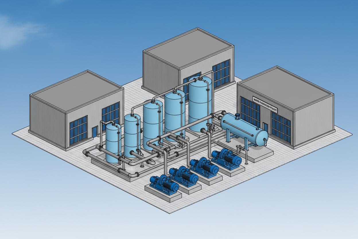
Intelligent 3D plant model with equipment, piping, and structural steel
Intelligent 3D plant modelling revolutionises the design, construction, and operation of industrial facilities. Unlike static 2D drawings, a 3D model contains embedded data – material specifications, weight, centre of gravity, vendor details, and maintenance history – that transforms the model into a living digital twin. From the 3D model, we automatically extract orthographic plans, sections, elevations, isometrics, and bill of materials with perfect consistency. Change a valve size in the model, and every drawing, schedule, and report updates simultaneously.
Reynolds & Bauhm builds 3D models in AutoCAD Plant 3D, AVEVA E3D, and Bentley OpenPlant with full piping specifications, equipment catalogues, and structural steel libraries. We perform clash detection across all disciplines, generate construction work packages, and hand over the completed model to operations as an as-built digital twin with full asset tagging for integration with CMMS and asset management systems.
Parametric equipment models with nozzle schedules, weight and centre of gravity data, vendor details, and maintenance access envelopes. Linked to P&ID equipment tags.
Spec-driven intelligent piping with automatic component placement, branch connections, and support generation. Extract isometrics and orthographics automatically.
Pipe racks, platforms, stairways, and equipment supports modelled with section sizes, connection details, and load paths. Export to structural analysis software.
Cable tray routing, conduit paths, lighting placement, and substation layout modelled in 3D with segregation from process piping and structural elements.
Ductwork routing, fan locations, and air handling unit placement with clash-free coordination against pipework and structural beams.
Foundation models, drainage routing, buried services, and paving levels integrated with process model for complete site visualisation.
Physical interferences between pipe and steel, cable tray and ductwork, or equipment and structure are identified and resolved in the model before construction. Our clash detection workflow processes weekly model updates against tolerance settings appropriate to construction phasing.
Clearance and accessibility issues that do not constitute physical interference but impede construction, operation, or maintenance are flagged and resolved. Soft clash categories include valve access, instrument readability, lifting zones, and insulation clearance.
Plans, elevations, and sections extracted directly from the 3D model with consistent scale, annotation, and dimensioning. Updates automatically when model changes.
Fabrication isometrics generated automatically with bill of materials, weld mapping, and dimensional take-offs. Spool splitting by transport and shop constraints.
Complete material lists by line, by area, or by construction work package with weights, quantities, and specification references for procurement.
Rendered images, walkthrough animations, and VR-compatible exports for stakeholder engagement, planning applications, and operator training.
As-built model with asset tags, serial numbers, maintenance schedules, and document links exported to CMMS (Maximo, SAP PM, or client system).
Engineering parameters that govern model fidelity, clash detection thresholds, and digital twin data completeness.
We align model element detail to BIM ISO 19650 and AIA G202 LOD definitions, calibrated for industrial process plants. Each discipline progresses through LOD 200 (conceptual geometry) to LOD 400 (fabrication-ready) prior to construction issue.
| LOD | Geometry | Information | Typical Use |
|---|---|---|---|
| 200 | Approximate size, shape, location | Tag, system, zone | Concept layout, optioneering |
| 300 | Accurate geometry, connections shown | Spec, material, performance data | Design development, HAZOP |
| 350 | Fabrication-level detail, supports | Vendor data, weight, COG | Construction issue, procurement |
| 400 | As-built geometry, deviations recorded | Serial numbers, test certs, manuals | Commissioning handover |
Clash matrices are run with discipline-specific tolerances to avoid false positives while catching genuine constructability issues. Weekly clash reports track open, reviewed, and resolved items against programme milestones.
AutoCAD Plant 3D (P3D), AVEVA E3D (2.1+), Bentley OpenPlant, and SolidWorks for equipment skids. All models maintain parametric relationships between geometry and data tables.
IFC 4.0 (ISO 16739), COBie UK 2012, NWD (Navisworks), STEP AP214, and DXF/DWG for 2D extraction. JSON/XML attribute exports for database ingestion.
Asset tag lists, equipment master data, and maintenance task lists exported to IBM Maximo, SAP PM, Infor EAM, and Microsoft Dynamics. Includes functional location hierarchies and spare-part BOM linkages.
FBX, glTF, and Unreal Engine Datasmith exports for real-time walkthroughs. 4K rendered stills and fly-through animations for planning committees and investor presentations.
Embedded calculation checks performed within the 3D environment or via linked CAESAR II and STAAD.Pro workflows.
Maximum support spans calculated per ASME B31.3 (process piping) and BS EN 13480. For carbon steel SCH 40 pipe at ambient: DN50 = 3.0 m; DN100 = 4.2 m; DN200 = 5.5 m; DN400 = 7.0 m. Insulated and plastic lines derated 15–25%.
Piping loads (weight, thermal expansion, surge) exported to STAAD.Pro or Tekla for pipe rack and platform design. Typical combined dead + live load allowance: 2.0–3.5 kN/m² for access platforms; 5.0–10.0 kN/m² for equipment decks.
Expansion loops, offsets, and expansion joint locations planned in 3D. Carbon steel expansion: 1.2 mm per 10 m per 10°C. Stainless steel 1.8 mm per 10 m per 10°C. Cold spring and anchor positions visualised before procurement.
Automatic slope validation: process lines minimum 1:400 toward drains; sewer lines 1:100; gravity gutters 1:200. Clash detection flags low-points where water can pocket before construction.
From conceptual layouts to construction-ready drawings, Reynolds & Bauhm delivers complete drafting and modelling services to global standards. Speak with our design engineers to scope your project.
Our expertise spans multiple industries with sector-specific water treatment solutions.