GA drawings for equipment, skids, containerised plants, and process buildings. Complete with dimensions, weights, nozzle schedules, lifting points, and foundation loads for fabrication, transport, and installation.
Intelligent 3D plant modelling in AutoCAD Plant 3D, AVEVA E3D, and Bentley OpenPlant.
Complete plant layout, piping design, and engineering drawing services.
P&ID process and instrumentation diagrams to ISA-5.1 and BS EN 1069 standards.
Intelligent pipe routing with clash detection, slope optimisation, and support span validation.
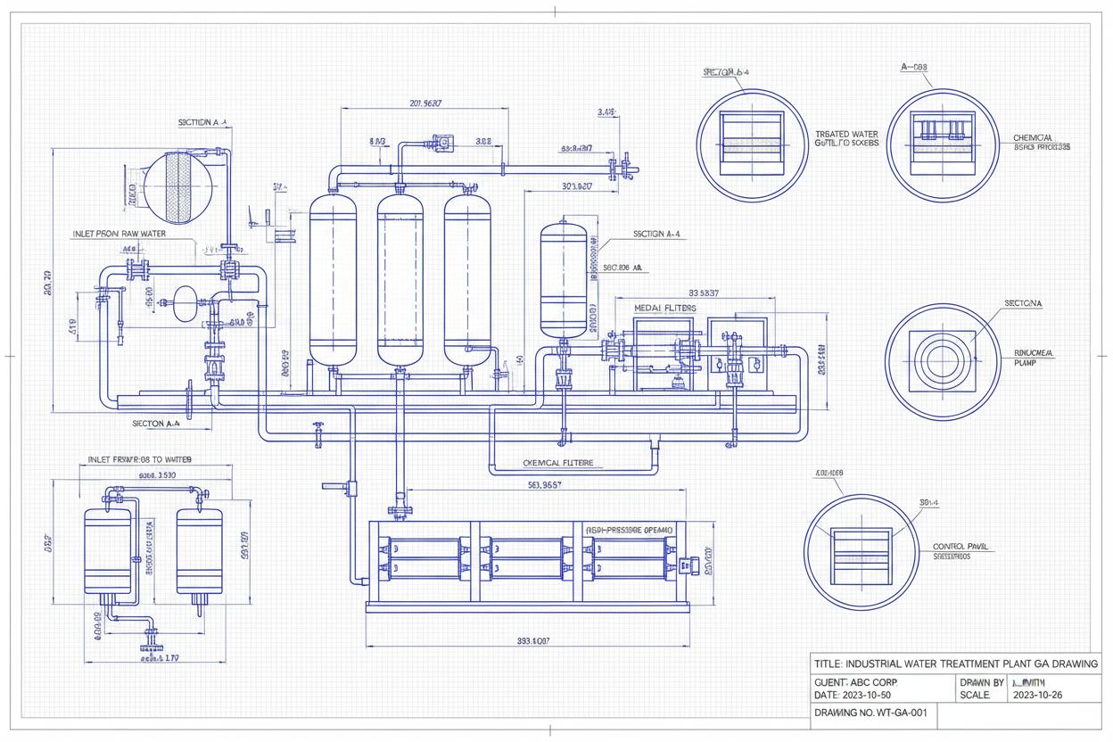
General arrangement drawing with dimensions, nozzles, and lifting points
General Arrangement (GA) drawings define the complete physical form of equipment, skids, and assemblies for fabrication, transport, installation, and maintenance. A properly drafted GA shows overall dimensions, weights, centre of gravity, nozzle positions and orientations, lifting lug locations, foundation bolt patterns, and maintenance access clearances. For packaged plant equipment such as DAF units, clarifiers, and containerised systems, the GA is the primary document that coordinates between process design, mechanical fabrication, civil engineering, and transport logistics.
Reynolds & Bauhm produces GA drawings for all equipment we design and supply. Our GAs are drafted in AutoCAD or SolidWorks with full dimensional chains, welded joint details, surface finish callouts, and reference to applicable fabrication codes. We provide GAs at tender stage for preliminary civil design, at approval issue for client sign-off, and at construction issue for fabrication release.
Overall length, width, height with chain and datum dimensions. Geometric tolerancing to BS EN ISO 1101 for critical interfaces and nozzle positions.
Empty, operating, and test weights with CofG coordinates for lifting, transport, and foundation design. Dynamic load factors for seismic and wind.
Inlet, outlet, drain, vent, and instrument nozzles with size, rating, facing, elevation, and orientation angles relative to equipment centreline.
Lifting lug positions, sling angles, transport envelope dimensions, and container loading constraints for road, rail, and sea freight.
Anchor bolt pattern, baseplate dimensions, point loads, and dynamic loads for civil engineer foundation design and soil bearing verification.
Removable panel positions, motor withdrawal paths, heat exchanger tube pull clearance, and crane hook reach envelopes.
Individual equipment drawings for DAF units, clarifiers, aerators, thickeners, and package treatment plants with full fabrication details.
Pre-fabricated skid assemblies showing mounted equipment, piping, instrumentation, and control panel arrangement on structural steel base.
ISO container modifications with equipment layout, access doors, ventilation, and utility connections for transportable treatment plants.
Process building drawings with equipment layouts, crane beams, door positions, floor loading, and HVAC coordination.
| ISO 5455 | Technical drawings – scales for general arrangement and detail views |
| BS EN ISO 1101 | Geometrical product specifications – tolerancing of form, orientation, location, and run-out |
| BS EN 1993-1-1 | Design of steel structures – general rules and rules for buildings (for structural GAs) |
| ASME Y14.5 | Dimensioning and tolerancing for North American projects and ASME-coded equipment |
| ISO 128-20 | Technical drawings – general principles of presentation for basic conventions for lines |
| BS 1192 | Collaborative production of architectural, engineering, and construction information (BIM level 2) |
| AIA Layer Guidelines | Layer naming and colour conventions for North American GA drawings |
| Client Specific | Shell DEP, BP EPS, ExxonMobil GP, and other major operator GA standards accommodated |
German standard for general arrangement drawings of pressure vessels and heat exchangers showing nozzle orientations and lifting lugs.
Unfired pressure vessels standard requiring GA drawings that demonstrate compliance with design by rule and design by analysis routes.
From conceptual layouts to construction-ready drawings, Reynolds & Bauhm delivers complete drafting and modelling services to global standards. Speak with our design engineers to scope your project.
Our expertise spans multiple industries with sector-specific water treatment solutions.