Multiphase CFD simulation of evaporative cooling towers. Model spray droplet distribution, fill pack airflow, fan power, and drift loss to optimise thermal rejection and minimise water consumption.
CFD thermal simulation services for water treatment equipment.
CFD thermal simulation for LED lighting enclosures and heat sinks.
CFD thermal mixing simulation for tanks, reactors, and process vessels.
CFD thermal simulation for LiDAR enclosures. Predict laser diode temperature, prevent optical window condensation, and validate.
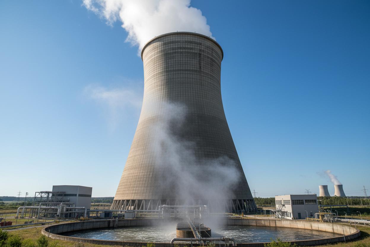
CFD airflow velocity contours in a counterflow cooling tower
Cooling towers reject waste heat to the atmosphere through evaporative cooling, consuming significant fan power and water in the process. Suboptimal airflow distribution, poor spray droplet breakup, and ineffective fill packing geometry reduce thermal rejection capacity and increase operating overheads. CFD thermal simulation enables precise optimisation of every component.
Our multiphase CFD models couple airflow, water spray, and heat/mass transfer to predict outlet water temperature, drift loss, and fan power consumption across the full meteorological operating envelope. We simulate counterflow, crossflow, and hybrid designs for industrial cooling duties from 1 MW to 500 MW thermal rejection.
Droplet size distribution, breakup length, and spatial coverage are modelled using Euler-Lagrange particle tracking to ensure uniform wetting of the fill pack.
Film flow, air-water contact area, and pressure drop through corrugated PVC or PP fill packs are simulated to optimise thermal rejection per unit volume.
Axial or centrifugal fan performance curves integrated with tower resistance to predict actual airflow and avoid stall or recirculation.
Droplet capture efficiency and pressure drop through chevron drift eliminators are simulated to minimise water loss while maintaining airflow.
Performance mapped across wet-bulb temperature, dry-bulb temperature, and relative humidity for all seasonal operating conditions.
Hybrid dry-wet operation and plume suppression systems modelled for urban and environmentally sensitive installations.
| Thermal Rejection | 1 – 500 MW (industrial scale) |
| Water Flow Rate | 100 – 50,000 m³/h |
| Approach Temperature | 3 – 8°C (above wet-bulb) |
| Cooling Range | 5 – 15°C (inlet to outlet) |
| Drift Loss | <0.001% of circulation flow |
| Fan Power | 0.03 – 0.06 kW/tonne refrigeration |
| Fill Depth | 0.6 – 1.8 m (film fill) |
| Materials | PVC, PP, FRP, concrete, stainless steel |
A 300 MW combined-cycle gas turbine plant experienced summer derating due to elevated cooling water temperatures. CFD thermal simulation of the existing counterflow tower identified severe airflow maldistribution caused by damaged fill packs and an oversized spray zone that created a bypass path around the fill. The CFD model predicted a 3.2°C improvement in cold water temperature by replacing the fill with higher-efficiency film packing, relocating spray nozzles, and trimming the fan blade angle. Post-modification field measurements confirmed a 2.9°C improvement, enabling full summer load capacity and avoiding in lost generation output.
Improved from 32.1°C to 29.2°C during peak summer ambient conditions.
Full 300 MW capacity maintained during previously derating conditions.
annual avoided output loss from summer derating elimination.
External and internal forced convection with turbulent boundary layers, entrance effects, and developing flow regions accurately captured using low-Reynolds turbulence models.
Buoyancy-driven flow from density variations with Boussinesq and full compressible formulations for high Rayleigh number applications including solar heating and passive cooling.
Nucleate pool boiling, flow boiling, and film condensation with heat transfer coefficient correlations validated against Rohsenow and Nusselt analytical solutions.
Surface-to-surface radiation and participating media radiation for high-temperature dryers, furnaces, and combustion applications with view factor calculation.
Heat transfer through packed beds, filter media, and insulation with effective thermal conductivity and non-thermal equilibrium between fluid and solid phases.
Electrical resistance heating in immersed heaters, trace heating, and electrocoagulation cells with coupled electrical potential and energy equations.
Every CFD thermal simulation undergoes rigorous validation before design recommendations are issued. We correlate model predictions against analytical solutions, established empirical correlations, and field measurement data from commissioned installations. Our validation protocol ensures that thermal predictions are accurate to within ±5% for outlet temperatures, ±10% for heat transfer coefficients, and ±15% for transient thermal response times.
Laminar pipe flow Graetz solution, flat plate Blasius thermal boundary layer, and sphere Nusselt number correlation agreement.
Dittus-Boelter, Gnielinski, and Petukhov correlations for turbulent tube flow within ±8% agreement across Reynolds range.
Over 50 commissioned installations with measured outlet temperatures, heat duties, and mixing times for model calibration.
External and internal forced convection with turbulent boundary layers, entrance effects, and developing flow regions accurately captured using low-Reynolds turbulence models.
Buoyancy-driven flow from density variations with Boussinesq and full compressible formulations for high Rayleigh number applications including solar heating and passive cooling.
Nucleate pool boiling, flow boiling, and film condensation with heat transfer coefficient correlations validated against Rohsenow and Nusselt analytical solutions.
Surface-to-surface radiation and participating media radiation for high-temperature dryers, furnaces, and combustion applications with view factor calculation.
Heat transfer through packed beds, filter media, and insulation with effective thermal conductivity and non-thermal equilibrium between fluid and solid phases.
Joule heating in immersed heaters, trace heating cables, and electrocoagulation cells with coupled electrical potential and energy equations.
Typical turnaround is 2-4 weeks for steady-state analysis and 4-8 weeks for transient simulations, depending on geometry complexity and mesh density.
STEP, IGES, or native CAD files (SolidWorks, Inventor, CATIA) are preferred. 2D drawings with critical dimensions are acceptable for simpler geometries.
Yes, our CFD-based performance predictions are backed by contractual guarantees when validated against pilot testing or field correlation.
Yes, we model boiling, condensation, freezing, melting, and evaporation using volume-of-fluid, mixture, and Eulerian-Eulerian multiphase approaches.
Typical projects vary from for single-component analysis to for full system optimisation with parametric studies.
Yes, we recommend combined CFD + pilot testing for high-value projects, using CFD to design the pilot and pilot data to validate the full-scale model.
CFD thermal simulation identifies hotspots, thermal gradients, and inefficiencies before capital is committed. Speak with our thermal simulation engineers to model your heat transfer challenge.
Our expertise spans multiple industries with sector-specific water treatment solutions.