CFD thermal simulation for street, industrial, horticultural, and automotive LED luminaires. Predict junction temperature, optimise heat sink geometry, and validate lifetime warranties under real-world solar and ambient loading.
CFD thermal simulation services for water treatment equipment.
CFD thermal mixing simulation for tanks, reactors, and process vessels.
CFD thermal simulation for LiDAR enclosures. Predict laser diode temperature, prevent optical window condensation, and validate.
CFD thermal simulation for automotive electronic enclosures. ECU, BMS, ADAS controller, and infotainment thermal management.
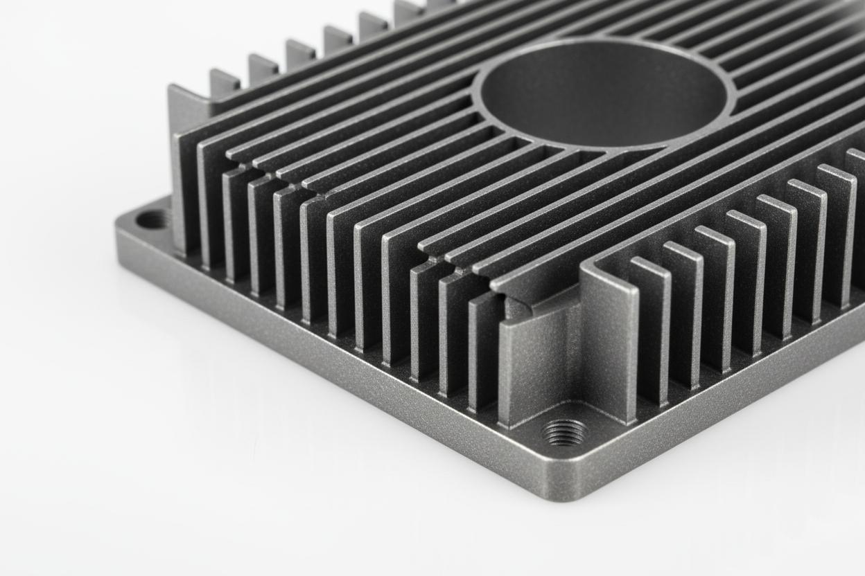
CFD temperature field on a streetlight LED heat sink array
LED efficiency and lifetime are exponentially sensitive to junction temperature. Every 10°C rise above 85°C junction halves the LED lifetime and reduces luminous efficacy by 3-5%. High-power street lighting, industrial high-bay luminaires, horticultural grow lights, and automotive headlamps all generate significant heat flux densities – often 0.5-2 W/cm² on the LED die – that must be removed through the MCPCB, thermal interface, heat sink, and ultimately to ambient air. Passive heat sinks, heat pipes, and active fan cooling each present optimisation challenges that rule-of-thumb design cannot resolve.
Reynolds & Bauhm's LED enclosure CFD models resolve the complete thermal path from LED junction to ambient with conjugate heat transfer. We simulate heat sink fin arrays with natural and forced convection, heat pipe vapour chamber spreading, thermal interface material contact resistance, and MCPCB copper trace conduction. Results predict junction temperature under worst-case ambient and solar loading, validate warranty claims, and optimise material and geometry for cost-performance trade-offs.
High-power COB and SMD arrays in IP66 housings with passive cooling. Model solar gain on dark enclosures, wind convection, and pole-top thermal resistance for 50,000-hour warranty validation.
200W-500W high-bay luminaires in hot factory ceilings with limited airflow. Heat pipe and vapour chamber spreading analysis for compact, lightweight designs.
High-PPFD LED arrays with passive and liquid-cooled heat sinks in humid greenhouse environments. Model condensation risk and corrosion on aluminium fins.
Compact LED and laser headlamp modules with severe space constraints. Model under-hood thermal soak, headlamp housing conduction, and DRL continuous operation heating.
Corrosion-resistant anodised aluminium and stainless steel heat sinks for coastal and offshore platforms. Model salt spray corrosion impact on fin thermal performance over 10-year life.
Fully submerged LED enclosures where water provides excellent cooling but sealing and galvanic corrosion dominate. Model conduction through stainless or titanium walls to flowing water.
| LED Junction Temperature Target | <85°C (high reliability), <105°C (standard) |
| Thermal Resistance (junction-case) | 1.0 – 8.0 K/W (package dependent) |
| MCPCB Thermal Resistance | 0.5 – 3.0 K/W (dielectric thickness dependent) |
| Thermal Interface Resistance | 0.1 – 1.0 K/W (grease vs pad vs phase-change) |
| Heat Sink Thermal Resistance | 0.3 – 5.0 K/W (fin geometry & airflow dependent) |
| LED Heat Flux | 0.5 – 2.0 W/cm² (high-power COB arrays) |
| Natural Convection HTC | 5 – 15 W/m²K (vertical fin, still air) |
| Forced Convection HTC | 25 – 100 W/m²K (fan-cooled heat sink) |
A European smart city programme required 10,000 LED streetlights with 100,000-hour lifetime and <10% lumen depreciation at 25 years. The initial die-cast aluminium heat sink design with radial fins achieved a simulated junction temperature of 94°C at 35°C ambient with 800 W/m² solar load – exceeding the 85°C warranty threshold. CFD thermal simulation with full conjugate heat transfer through the MCPCB, TIM, and heat sink predicted that the radial fin array suffered from severe thermal plume interaction, where hot exhaust air from lower fins recirculated into upper fin inlets, reducing effective convection by 30%. We redesigned the heat sink with split arrays, chimney-effect vertical channels, and aerodynamic top vents that harnessed wind pressure regardless of direction. The CFD-optimised design reduced junction temperature to 78°C at identical ambient – a 16°C improvement – while reducing aluminium mass by 22% (saving ±12 per luminaire, or ±120,000 across the programme). Measured junction temperatures on 50 prototype units averaged 79.3°C, confirming the CFD prediction within ±2°C and validating the 100,000-hour warranty.
Reduced from 94°C to 78°C – below the 85°C warranty threshold.
22% aluminium mass reduction saved ±120,000 across 10,000 luminaires.
100,000-hour warranty validated with measured junction at 79.3°C ±2°C.
Forward voltage and current at rated and worst-case drive conditions. Heat generation distributed across die, phosphor, and substrate.
Conjugate conduction through die-attach, slug, MCPCB dielectric, copper trace, TIM, and heat sink base with spreading resistance.
Fin array natural or forced convection with buoyancy and wind effects. Surface-to-surface radiation from hot fins to sky and ground.
Solar absorptivity of enclosure paint and lens material. Diurnal and seasonal ambient temperature and wind speed variations.
Phosphor temperature affects CCT and CRI. Model Stokes heat, phosphor quantum efficiency, and re-absorption in multi-die packages.
Junction temperature table, heat sink thermal resistance, airflow streamlines, and design recommendations with cost-performance analysis.
LED lumen maintenance testing and lifetime projection methodology. Our CFD predictions inform LM-80 test conditions and drive current selection.
Luminaire safety standard covering thermal endurance, resistance to heat, and fire enclosure requirements for LED lighting equipment.
Electrical and photometric measurements of solid-state lighting products at thermal equilibrium – CFD predicts the steady-state temperature.
Safety standard for LED equipment in lighting products, covering thermal management, electrical isolation, and environmental suitability.
Ingress protection for outdoor luminaires – IP65, IP66, and IP67 validated with dust and water jet testing alongside thermal performance.
European conformity for luminaires including electromagnetic compatibility, thermal safety, and RoHS material compliance.
CFD enclosure thermal simulation predicts internal temperatures, identifies hotspots, and validates cooling strategies before prototype fabrication. Speak with our thermal engineers to safeguard your electronics.
Our expertise spans multiple industries with sector-specific water treatment solutions.