CFD simulation for underground construction and metro ventilation. Model TBM heat dissipation, piston effect airflow, fire smoke propagation, and HVAC performance for worker safety and passenger comfort.
CFD thermal simulation services for water treatment equipment.
CFD thermal simulation for LED lighting enclosures and heat sinks.
CFD thermal mixing simulation for tanks, reactors, and process vessels.
CFD thermal simulation for LiDAR enclosures. Predict laser diode temperature, prevent optical window condensation, and validate.
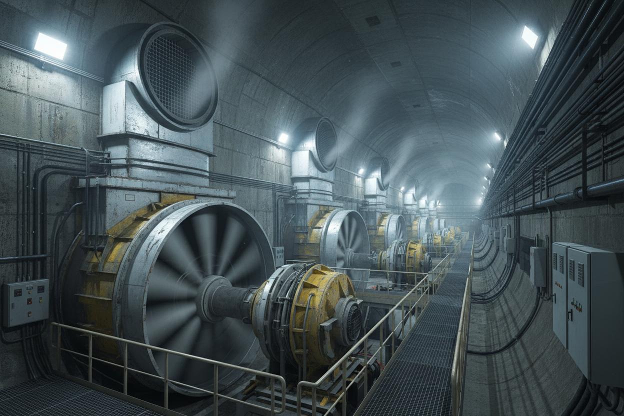
CFD velocity and temperature field in a metro tunnel during TBM operation
Underground construction and metro operations generate significant thermal loads from TBM motors, grout curing, concrete hydration, diesel equipment, and passenger metabolism. Inadequate ventilation leads to heat stress for workers, reduced equipment efficiency, and accelerated concrete curing that creates thermal cracking. During operational metro service, piston effect airflow, HVAC system performance, and fire smoke management all depend on accurate thermal and airflow prediction that only CFD can provide.
Our tunnel ventilation CFD models simulate transient airflow driven by trains, jet fans, and natural stack effect, coupled with heat sources from equipment, personnel, and ground conduction. We predict air temperature, velocity, and contaminant concentration at every critical location to inform ventilation system design, emergency smoke extraction, and worker safety protocols.
Transient airflow driven by train movement in tunnels and stations. Predict air velocity, temperature rise, and pressure transients for passenger comfort and door operation.
Thermal management during tunnel boring machine operation. Motor heat, grout exotherm, and friction heat modelled with ventilation and chilled water cooling.
Smoke propagation, temperature stratification, and visibility analysis for emergency ventilation design. Jet fan and extraction system sizing with critical velocity calculation.
Forced ventilation design for cut-and-cover excavations and mined tunnels. Diesel exhaust dilution, heat stress prevention, and dust suppression optimisation.
Platform and concourse air conditioning design with heat loads from passengers, trains, lighting, and equipment. Predict cooling capacity and supply air distribution.
Natural and mechanical ventilation of deep shafts and adits. Stack effect, ground temperature, and moisture condensation analysis for shaft infrastructure protection.
| Tunnel Cross-Section | 20 – 80 m² (single/double track) |
| Train Heat Output | 200 – 500 kW per train (traction + braking) |
| TBM Heat Output | 500 – 2,000 kW (cutterhead + motors) |
| Grout Exotherm | 40 – 80°C peak temperature (cement dependent) |
| Worker Comfort Limit | 28°C wet-bulb temperature (WBGT < 30°C) |
| Air Velocity (normal) | 1.5 – 3.0 m/s (piston effect) |
| Air Velocity (fire) | >3.0 m/s critical velocity (smoke control) |
| Ventilation Fan Power | 50 – 500 kW per jet fan (tunnel dependent) |
A major metro extension project with 8.5 km of twin-bore tunnels required thermal management during TBM operation to maintain worker safety and grout quality. The TBMs generated 1,200 kW of heat from cutterhead motors, hydraulic systems, and grout pumps. Initial ventilation design using empirical methods indicated that 60 m³/s of supply air would maintain temperatures below 28°C. However, field measurements during the first 500 m of drive showed peak temperatures of 31°C at the backup gantry, forcing shift reductions and grout retarder additions. Reynolds & Bauhm conducted transient CFD thermal simulation of the TBM backup zone with all heat sources, ground conduction, and the existing ventilation system. The model identified that 40% of the supply air was short-circuiting past the cutterhead due to the annular gap geometry, leaving the backup zone under-ventilated. The CFD model recommended: (1) relocating the supply duct outlet to the crown ahead of the cutterhead, (2) installing exhaust ducts at the shield tail to capture hot air, and (3) adding two 100 kW chilled water coils at the backup gantry. Post-modification, maximum temperatures stabilised at 26.5°C, shift productivity increased 15%, and grout set times became consistent, eliminating retarder requirements.
Maximum TBM zone temperature reduced from 31°C to 26.5°C consistently.
Shift productivity increased 15% with restored full-shift working duration.
grout retarder elimination plus reduced shift premium costs.
Tunnel, station, shaft, and TBM CAD models prepared with cross-passages, adits, and ventilation duct routing.
Equipment heat output, passenger metabolic heat, train regenerative braking, and ground conduction temperature boundary conditions.
Moving mesh or sliding interface train motion with compressible flow for pressure transients and airflow reversal.
Jet fans, supply/exhaust ducts, and shaft ventilation modelled with fan curves and damper positions.
Fire heat release rate (HRR) with buoyant smoke layer development, critical velocity, and tenability criteria for evacuation.
Temperature and velocity contour animations, heat balance summaries, ventilation adequacy assessment, and design optimisation.
External and internal forced convection with turbulent boundary layers, entrance effects, and developing flow regions accurately captured using low-Reynolds turbulence models.
Buoyancy-driven flow from density variations with Boussinesq and full compressible formulations for high Rayleigh number applications including solar heating and passive cooling.
Nucleate pool boiling, flow boiling, and film condensation with heat transfer coefficient correlations validated against Rohsenow and Nusselt analytical solutions.
Surface-to-surface radiation and participating media radiation for high-temperature dryers, furnaces, and combustion applications with view factor calculation.
Heat transfer through packed beds, filter media, and insulation with effective thermal conductivity and non-thermal equilibrium between fluid and solid phases.
Joule heating in immersed heaters, trace heating cables, and electrocoagulation cells with coupled electrical potential and energy equations.
Typical turnaround is 2-4 weeks for steady-state analysis and 4-8 weeks for transient simulations, depending on geometry complexity and mesh density.
STEP, IGES, or native CAD files (SolidWorks, Inventor, CATIA) are preferred. 2D drawings with critical dimensions are acceptable for simpler geometries.
Yes, our CFD-based performance predictions are backed by contractual guarantees when validated against pilot testing or field correlation.
Yes, we model boiling, condensation, freezing, melting, and evaporation using volume-of-fluid, mixture, and Eulerian-Eulerian multiphase approaches.
Typical projects vary from for single-component analysis to for full system optimisation with parametric studies.
Yes, we recommend combined CFD + pilot testing for high-value projects, using CFD to design the pilot and pilot data to validate the full-scale model.
CFD thermal simulation identifies hotspots, thermal gradients, and inefficiencies before capital is committed. Speak with our thermal simulation engineers to model your heat transfer challenge.
Our expertise spans multiple industries with sector-specific water treatment solutions.